It is good design to include this resistor, but if speed is not an issue then the resistor can be omitted. Including it enables the charge stored in this capacitor to dissipate and this aids a faster turn-off. Without the resistor in place, there is no discharge path for any charge held in the capacitor formed by the base emitter junction. The bypass resistor is included to aid the switch-off process. Darlington transistor with base-emitter resistor

Base emitter bypass resistorĪlthough the Darlington pair circuit is often used in its basic format, it is often seen with a bypass resistor between the base and emitter connections of the final transistor. This enormous level of current gain is very useful in many circuit designs, especially where low impedance loads need to be driven with high current levels. This means that if two transistors with modest current gains of 50 were used, then the overall current gain would be 50 x 50 = 2500.

The overall current gain of the Darlington pair is the product of the two individual transistors:

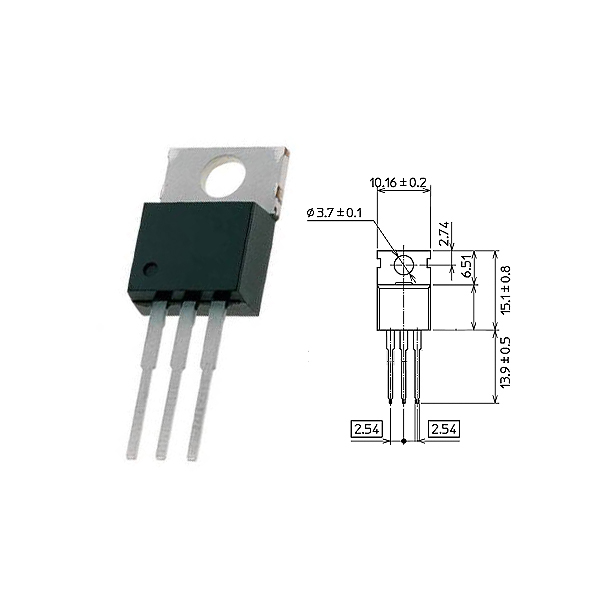
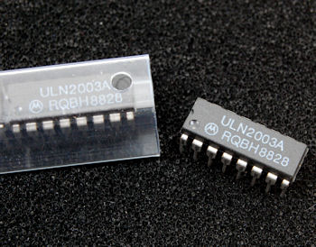
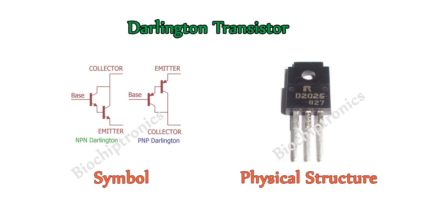
This results in a very high level of current gain. In this way the base current from the first transistor enters the base of the second. The emitter of the input transistor is connected directly to the base of the second. It normally consists of two transistors, although in theory it can contain more. The Darlington pair circuit configuration is quite distinctive. This makes Darlington transistor pairs very easy to use and incorporate into new electronic circuit designs. Typically these are contained within an IC package as these are often used to drive displays, etc. Many Darlington arrays are also available where several Darlington transistor pairs are contained within the same package. two transistors, or it is also possible to obtain them as a single electronic component with the two transistors integrated onto one chip. The idea covered the idea of having two or three transistors on a single chip where the emitter of one transistor was connected to the base of the next, and all the transistors in the Darlington configuration shared the same collector.ĭarlington pair transistor circuits can be bought as individual electronic components, i.e. The circuit configuration was invented at Bell Laboratories by Sidney Darlington in 1953 at the time when a significant amount of work was being undertaken into transistor development. The Darlington Pair may sometimes also be referred to as a super-alpha pair, but this name is used less these days. Nevertheless, where applicable, the Darlington Pair is able to provide many advantages over a single transistor circuit configuration. However the Darlington Pair does have some drawbacks and as a result it is not suitable for all high gain applications. Basic Darlington Pair transistor configuration It is primarily used because it offers a particularly high current gain and this also reflects into a high input impedance for the overall Darlington circuit when compared to a single transistor. The Darlington Pair offers a number of advantages.

One transistor circuit configuration that can be used to very good effect in many instances is the Darlington Pair. See also: Transistor circuit design Transistor circuit types Transistor Darlington Pair A summary or tutorial explaining the Darlington Pair transistor circuit configuration, with essentials for circuit design and operation.ĭarlington pair Darlington circuits Darlington design Sziklai pair Darlington / Sziklai output pair


 0 kommentar(er)
